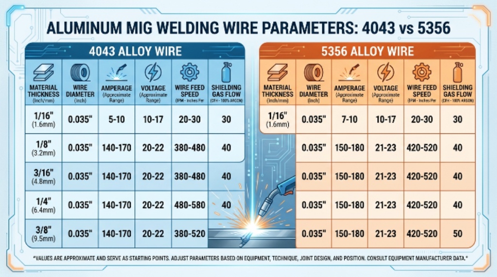

If you are looking for the right aluminum MIG welding wire speed and voltage, there is one important thing to understand first: there is no single voltage-and-wire-speed setting that works for every aluminum MIG welder.
Your actual settings depend on aluminum thickness, filler-wire diameter and alloy, welding machine output, transfer mode, shielding gas, gun setup, travel speed, joint design, and whether your machine uses conventional voltage controls or a synergic/trim-based program.
That is why a good aluminum MIG chart should be used as a starting point, not as a universal recipe.
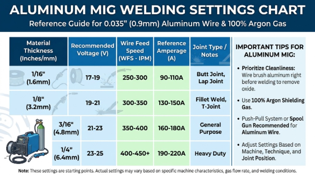
The chart below gives practical starting guidance, while the sections that follow explain how to fine-tune the settings without chasing numbers blindly.
Quick Aluminum MIG Settings Chart
For most conventional aluminum MIG applications, 100% argon is the standard starting shielding gas. Miller’s current guidance also emphasizes using the welder’s own parameter chart because aluminum settings vary substantially by machine and spool-gun combination.
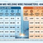
| Aluminum thickness | Common wire diameter | Practical starting point | What to watch |
| 1/16 in. | .030 in. | Use the machine’s thin-aluminum program/chart; start at the low end of its recommended range | Burn-through and distortion |
| 1/8 in. | .030–.035 in. | Moderate-to-high WFS with machine-specific voltage/trim | Fusion and heat buildup |
| 3/16 in. | .035–.047 in. | Higher WFS and sufficient machine output | Incomplete fusion |
| 1/4 in. | .035–.062 in. | High-output setup; follow the machine/filler procedure | Machine capacity and heat input |
Important: Do not copy a voltage number from one welder to another and assume it will produce the same arc. Some modern systems use synergic programs, trim, arc control, or relative voltage scales. Lincoln specifically notes that on some of its Power Mode systems, the displayed Volts/Trim value does not correspond directly to actual welding voltage.
For that reason, a manufacturer’s chart for your exact machine is more authoritative than a generic internet chart.
Why Aluminum MIG Settings Are Different From Steel
Aluminum changes the way a MIG welder behaves.
It has high thermal conductivity, so heat moves rapidly away from the weld zone. At the same time, the aluminum surface develops an oxide layer that behaves very differently from the underlying metal.
AWS notes that aluminum’s combination of thermal behavior and relatively low melting temperature can make the material transition from apparently cold to overheated surprisingly quickly. Proper cleaning and preparation are therefore critical.
This creates a common beginner mistake:
A weld that looks cold at the beginning of a pass can become excessively hot only a few seconds later.
If you compensate by simply increasing voltage or wire speed, you may make the problem worse.
Aluminum MIG generally rewards:
- Clean base metal
- Correct filler alloy
- Correct wire diameter
- Adequate machine output
- Reliable wire feeding
- 100% argon in typical setups
- Consistent travel speed
- A controlled push technique
- Short test beads before welding the actual part
Aluminum MIG Wire Speed: What the Numbers Really Mean
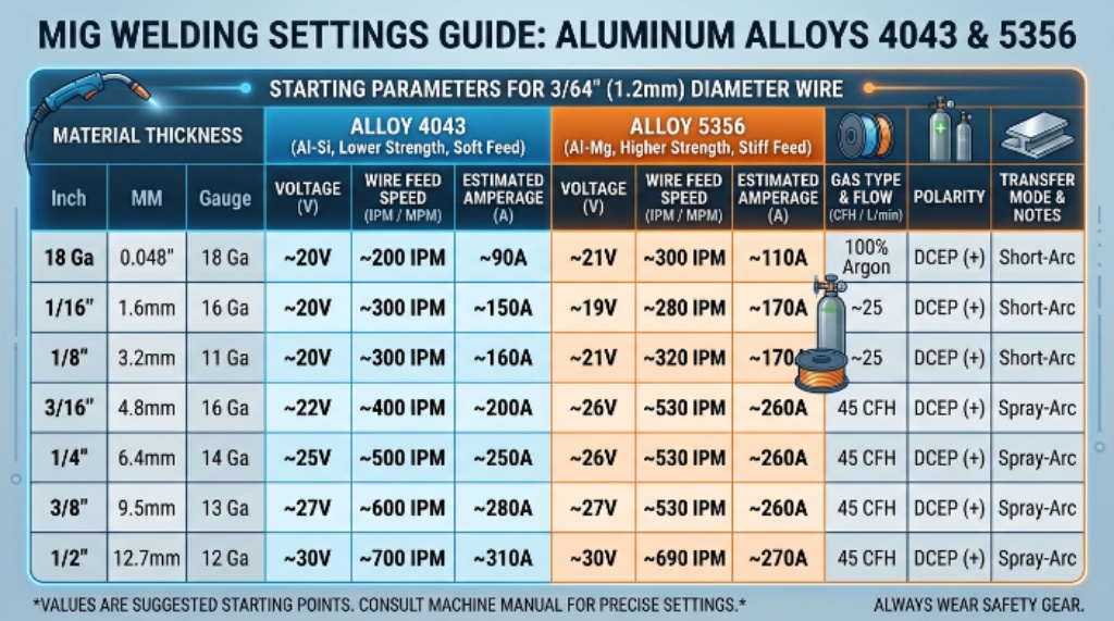
Wire feed speed, or WFS, is normally expressed in inches per minute (IPM) in U.S. welding equipment.
WFS is important because it controls how much filler wire enters the arc. On conventional constant-voltage MIG systems, increasing WFS generally increases welding current because the machine has to melt more wire.
Miller’s current aluminum guidance lists these typical ranges for common aluminum filler-wire diameters:
| Aluminum wire diameter | Typical current range | Typical wire-speed range |
| .030 in. | 100–150 A | 500–600 IPM |
| .035 in. | 85–190 A | 480–740 IPM |
| .047 in. | 125–240 A | 260–470 IPM |
| .062 in. (1/16 in.) | 190–340 A | 265–420 IPM |
These are typical parameter ranges, not a universal setting chart. Notice that a larger wire does not necessarily mean a proportionally higher IPM number. Wire diameter changes the amount of metal deposited per unit length, so WFS cannot be compared between diameters as though the numbers were interchangeable.
That is one reason simply saying “set aluminum to 600 IPM” is poor advice.
What Voltage Does in Aluminum MIG Welding
Voltage primarily influences arc length and the overall shape and width of the weld bead.
In a conventional MIG setup:
- Too little voltage can produce a short, unstable arc and a high or rope-like bead.
- Too much voltage can create an excessively long arc, a very flat bead, excess heat, and other instability.
- The correct setting produces a controlled arc with appropriate wetting and fusion.
However, the exact voltage number depends heavily on the power source.
For example, Lincoln’s documentation for Power Mode gives aluminum procedures in terms of wire feed speed and a trim/control value, rather than treating the displayed number as a universal voltage. The company explicitly states that its Volts/Trim display is a relative value on applicable systems.
That means a generic chart saying “use 21 volts for 3/16-inch aluminum” can be misleading unless it specifies the machine, process, wire, transfer mode, gas, and procedure behind that number.
The better approach
- Identify the exact welder.
- Select the aluminum program or process recommended by the manufacturer.
- Select the correct wire diameter and alloy.
- Enter the material thickness.
- Set WFS and voltage/trim according to the machine’s chart.
- Make a test weld on matching scrap.
- Fine-tune one variable at a time.
That process is much more reliable than copying a generic voltage value.
4043 vs. 5356 Aluminum MIG Wire
Choosing the filler wire is just as important as choosing the settings.
The two aluminum filler alloys most commonly encountered by MIG welders are ER4043 and ER5356. Miller and Hobart both emphasize that these fillers are widely used but are not universally interchangeable.
ER4043
4043 is an aluminum-silicon filler alloy.
It is popular because it generally offers:
- Good weldability
- Good puddle fluidity
- Smooth bead appearance
- Reduced sensitivity to some hot-cracking problems
- Good performance for many common aluminum applications
Miller describes 4043 as a particularly approachable option for many DIY and general-purpose aluminum MIG jobs.
4043 can also produce a cleaner-looking weld with less smut than some alternatives.
ER5356
5356 is an aluminum-magnesium filler alloy.
It is often selected when the application requires characteristics such as:
- Higher strength
- Better ductility and toughness
- Better anodized color matching
- Good wire feedability because the wire is stiffer
Hobart’s aluminum guide specifically notes that 5356 is approximately twice as stiff as 4043/4943, which can make it easier to feed through a welding system.
But 5356 is not automatically the better filler.
For example, Hobart states that 5356 should not be used for long-term service above approximately 150°F in applications where the filler-selection criteria rule it out; 4043/4943 or another suitable filler may be preferred in those situations.
ESAB likewise cautions against treating 4043 and 5356 as interchangeable for every aluminum alloy.
Filler Metal Selection Comes Before Settings
Before adjusting voltage or WFS, identify the base aluminum alloy whenever possible.
For common 6xxx-series aluminum and some 5xxx-series materials, either 4043/4943 or 5356 may be acceptable depending on the application. But the choice changes when strength, elevated temperature, corrosion resistance, anodizing, ductility, or cracking behavior becomes important.
For example, Hobart’s current selection guidance says:
- 5356 is generally favored for higher ductility and toughness.
- 5356 is preferred when anodized color matching is important.
- 4043/4943 can be preferred for reduced distortion and termination/shrinkage cracking.
- 4043/4943 is preferred for long-term elevated-temperature service in situations where 5356 is unsuitable.
- Some 5xxx-series alloys with higher magnesium content require 5356 rather than 4043/4943.
For structural, pressure, marine, vehicle, or other safety-critical components, do not choose filler solely from a beginner chart. Use the applicable filler-metal selection chart, WPS, engineering specification, or qualified welding procedure.
What Shielding Gas Should You Use?
For conventional aluminum MIG welding, 100% argon is the normal starting gas.
Lincoln’s aluminum documentation specifies 100% argon for its aluminum MIG/Power Mode procedures, and Miller’s current aluminum guidance likewise uses 100% argon for common spool-gun setups.
Do not automatically use the 75/25 argon-CO₂ mixture commonly used for mild-steel MIG.
Also pay attention to gas coverage. Porosity can result from:
- Insufficient gas flow
- Excessive gas flow causing turbulence
- Wind
- Dirty material
- Moisture
- Poor nozzle positioning
- Leaks in the gas system
If the weld contains pinholes or porosity, do not immediately start changing voltage.
Check the material and shielding system first.
Spool Gun vs. Push-Pull Gun
Feeding aluminum wire is another major difference from welding steel.
Aluminum wire is soft, particularly 4043. Trying to push it through a long conventional MIG gun can cause:
- Birdnesting
- Wire buckling
- Erratic feeding
- Burnback
- Contact-tip problems
A spool gun places a small spool of wire directly on the gun, dramatically shortening the distance the soft wire has to travel.
A push-pull system uses a motor at the feeder and another motor near the gun to help move the wire through the cable.
Miller recommends spool guns or push-pull systems for many aluminum applications because they improve feedability and reduce the problems associated with pushing soft wire through a long gun.
AWS also points out that push-only aluminum welding is possible in some circumstances, but the setup is much more demanding. For push-only systems, AWS recommends particular attention to filler type, wire diameter, torch length, and keeping the feed path as straight as practical.
Aluminum MIG Setup Checklist
Before striking an arc, run through this checklist.
1. Identify the aluminum
Determine the base alloy and thickness if possible.
2. Choose the filler
Select ER4043, ER5356, or another appropriate filler based on the application—not merely convenience.
3. Select the wire diameter
For many general-purpose aluminum MIG jobs, .030 and .035 inch wire are common choices. Miller specifically recommends these sizes for many home and general-maintenance applications.
4. Use the correct feeding system
A spool gun or push-pull setup is generally easier for soft aluminum wire.
5. Install the correct contact tip and drive rolls
The consumables must match the wire diameter and aluminum-feed system.
6. Use 100% argon
Follow the specific machine and filler manufacturer’s recommendation.
7. Clean the aluminum
Remove oil, dirt, paint, moisture, and surface contamination. Remove the oxide layer with an appropriate dedicated stainless-steel brush or other suitable preparation method.
8. Set the machine
Use the manufacturer’s aluminum program or parameter chart first.
9. Make a test weld
Use scrap aluminum with the same alloy and thickness whenever possible.
10. Adjust one variable at a time
If you change WFS, voltage, travel speed, stickout, and gun angle simultaneously, you will not know what fixed—or caused—the problem.
Common Aluminum MIG Problems
| Problem | Likely causes | First thing to check |
| Birdnesting | Soft wire, excessive drive tension, poor liner/feed path | Spool gun, drive rolls, liner, tension |
| Burnback | Poor feeding, incorrect contact tip, excessive heat | Wire feed and contact tip |
| Porosity | Contamination or inadequate shielding | Cleaning and gas coverage |
| Black soot | Contamination, poor arc control, shielding problems | Clean the joint and verify gas |
| Cold-looking bead | Insufficient heat or poor travel technique | Machine output, WFS, arc length and cleaning |
| Burn-through | Excessive heat or slow travel | Reduce heat and/or increase travel speed |
| Poor fusion | Insufficient heat, oxide contamination, poor joint preparation | Cleanliness and machine capacity |
A settings chart cannot solve a mechanical feeding problem. If the wire is slipping, birdnesting, or intermittently stopping, fix the feed system before making large changes to the welding parameters.
How to Fine-Tune Aluminum MIG Settings
Once the machine is configured, make a short test bead.
Watch the puddle rather than relying only on sound.
You want to see the molten metal wet into both sides of the joint without excessive soot, porosity, or an obviously cold, rope-like profile.
If the arc is unstable, work through the variables systematically:
First: check wire feeding.
Second: check material cleanliness.
Third: check gas coverage.
Fourth: verify wire alloy and diameter.
Fifth: check machine output.
Only then: fine-tune voltage/trim and WFS.
This order matters because welders often try to solve contamination or feeding problems by changing electrical settings.
Don’t Ignore Machine Capacity
A generic chart cannot compensate for an undersized power source.
Miller notes that aluminum’s thermal conductivity makes adequate machine output particularly important and recommends 230V-capable equipment for many DIY aluminum applications.
A small 120V welder may be perfectly useful for thin aluminum work, but that does not mean it can produce adequate fusion on 1/4-inch aluminum simply because an internet chart lists a voltage and WFS combination.
For thicker material, machine output, duty cycle, transfer mode, joint design, preheat requirements, and the number of passes all become increasingly important.
Should You Preheat Aluminum?
Preheating can sometimes be useful on thick aluminum, but it should not be used as a substitute for adequate welding equipment or an appropriate procedure.
Too much heat can increase distortion and make the puddle difficult to control.
For critical components, use the temperature limits and procedure specified for the material and filler rather than relying on a generic beginner recommendation.
Why the Original “Universal Voltage Chart” Approach Falls Short
A useful aluminum MIG chart should answer more than:
“What voltage and wire speed should I use?”
It should also tell you:
- What wire alloy is being used
- What wire diameter is being used
- What machine the setting applies to
- Whether the machine uses actual voltage or a trim/program value
- What shielding gas is required
- What transfer mode is being used
- What feeding system is being used
- What material thickness the setting targets
- Whether the numbers are manufacturer procedures or merely starting ranges
That distinction is particularly important because current manufacturer documentation demonstrates that different machines can express aluminum parameters in very different ways.
Frequently Asked Questions
What voltage should I use for aluminum MIG welding?
There is no universal aluminum MIG voltage. The correct voltage depends on the welder, wire diameter, filler alloy, material thickness, transfer mode, and machine control system. Start with the parameter chart for your specific welder and then fine-tune on matching scrap.
What wire speed should I use for aluminum MIG?
Typical Miller guidance lists approximately 500–600 IPM for .030-inch aluminum wire, 480–740 IPM for .035-inch wire, 260–470 IPM for .047-inch wire, and 265–420 IPM for 1/16-inch wire. These are broad ranges, not settings that should be copied blindly.
Is 4043 or 5356 better for aluminum MIG?
Neither is universally better. 4043 is often easier to weld and provides good fluidity and appearance. 5356 offers advantages such as higher strength, ductility, toughness, anodized color matching, and better feedability. The base-metal alloy and service requirements should determine the final choice.
Can I MIG weld aluminum without a spool gun?
Yes, but the answer depends on the feeding system and filler wire. Spool guns and push-pull systems make aluminum wire feeding much easier. AWS notes that push-only aluminum welding can be performed with appropriate equipment and technique, but soft wire and long gun cables create additional feeding challenges.
What gas should I use for aluminum MIG?
100% argon is the standard starting point for many conventional aluminum MIG applications. Always confirm the gas requirement in the welding machine and filler-metal documentation.
Why does my aluminum MIG weld have black soot?
Black soot can be associated with contamination, inadequate shielding, arc-length problems, or technique. Clean the aluminum thoroughly, verify argon flow and coverage, inspect the gun setup, and then evaluate the electrical settings.
Why does aluminum MIG wire keep birdnesting?
Birdnesting is usually a feeding problem rather than a voltage problem. Check the spool-gun or push-pull setup, drive-roll pressure, liner, contact tip, wire diameter, and spool tension. Aluminum wire is considerably softer than steel wire, so excessive drive-roll pressure can make feeding worse.
Can I use 75/25 gas for aluminum MIG?
75/25 argon-CO₂ is commonly used for mild steel, but it is not the normal shielding-gas choice for conventional aluminum MIG. 100% argon is the common starting gas for aluminum.
What size aluminum MIG wire should I use?
.030 and .035 inch are common sizes for many general-purpose aluminum MIG applications. Larger diameters such as .047 and 1/16 inch become useful as material thickness and required deposition increase. Always confirm the wire diameter against your machine and gun specifications.
Can I use this chart for a structural aluminum repair?
Not by itself. A generic chart is appropriate for learning and initial setup, but structural, marine, pressure-containing, vehicle, or otherwise safety-critical work should follow the applicable code, specification, WPS, filler-metal recommendation, and qualification requirements.
Bottom Line
The best aluminum MIG welding setting is not simply a number copied from a chart.
Start with the correct filler alloy, wire diameter, shielding gas, feeding system, and machine-specific parameter chart. Then make a test weld on aluminum that matches the actual job.
For many common setups, 100% argon and .030- or .035-inch aluminum wire are sensible starting points. ER4043 is a popular general-purpose choice, while ER5356 offers different strength, ductility, feedability, and anodizing characteristics. But neither filler should be selected without considering the base alloy and service conditions.
Most importantly, treat generic voltage and WFS figures as starting information, not a certified welding procedure. Your machine’s documentation and the applicable filler-metal data should take priority.
A clean joint, stable wire feed, adequate shielding, correct filler, and controlled travel speed will usually get you much closer to a sound aluminum MIG weld than endlessly adjusting voltage by a single volt.