


Choosing the right welding wire size is one of the first decisions you need to make when setting up a MIG or flux-core welder. The diameter of the wire affects the current range, wire-feed speed, deposition rate, heat input, feeding behavior, and how easily you can control the weld puddle.
But there is an important catch: wire diameter does not determine the correct weld by itself.
Your material thickness, welding process, wire classification, machine output, shielding gas, polarity, transfer mode, joint design, welding position, and even the gun’s drive-roll and contact-tip setup all matter.
For most beginners welding mild steel with gas-shielded MIG, .030-inch solid wire is a versatile starting point. For thin sheet metal, .023 or .024 inch can provide better control. And for heavier fabrication, .035 or .045 inch may make more sense if the welder has enough output.
This updated welding wire size chart explains where the common diameters fit, what they are good for, and how to choose a wire without relying on a one-size-fits-all chart.
Important: The numbers below are starting points, not universal welding procedures. Always give your welder’s owner’s manual and the wire manufacturer’s data priority over a generic chart. For production, structural, pressure-containing, lifting, or other safety-critical welding, follow the applicable qualified WPS and code requirements.
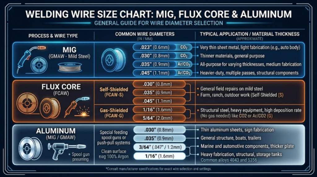
Quick Welding Wire Size Chart
| Wire diameter | Approx. metric size | Common process | Typical application |
| .023 in | 0.6 mm | Solid MIG | Very thin sheet metal, automotive panels |
| .024 in | 0.6 mm | Solid MIG | Thin steel and light fabrication |
| .030 in | 0.8 mm | Solid MIG / some flux core | General-purpose light to medium steel |
| .035 in | 0.9 mm | Solid MIG / flux core | Medium steel, repair and fabrication |
| .045 in | 1.1–1.2 mm | MIG / flux core | Heavier steel and higher-output machines |
| .052 in | 1.3 mm | Flux core | Heavy fabrication and specialized applications |
| 3/64 in | 1.2 mm | Aluminum MIG | Aluminum with spool gun or push-pull system |
These diameters are commonly available in commercial filler-metal lines. For example, ESAB currently lists ER70S-6 MIG wire in .023, .030, .035 and .045-inch diameters, while its product data identifies ER70S-6 under AWS A5.18.
MIG Welding Wire Size by Material Thickness
If you are welding mild steel with conventional short-circuit MIG, material thickness is a useful first filter for choosing wire diameter.
| Mild steel thickness | Practical starting wire | Typical use |
| 24–20 gauge | .023/.024 in | Thin sheet, body panels, light repair |
| 20–16 gauge | .023/.024 or .030 in | Sheet metal and light fabrication |
| 16–14 gauge | .030 in | General fabrication |
| 14–10 gauge | .030 or .035 in | Brackets, frames and repair work |
| 10 gauge–1/4 in | .035 in | Medium fabrication |
| 1/4–3/8 in | .035 or .045 in | Heavier fabrication, often multiple passes |
| 3/8 in and thicker | .045 in or larger | Higher-output, multi-pass applications |
These ranges should not be interpreted as a rule that says, for example, “.035 wire is automatically correct for 1/4-inch steel.” A machine’s amperage capacity and the joint design may make a bigger difference than the wire diameter alone.
A 240-volt machine capable of substantially more output can support wire sizes that would be impractical on a small 120-volt machine. Miller’s current Millermatic 255 specifications, for example, list solid-steel wire from .023 through .045 inch and flux-cored wire from .030 through .045 inch.
The key point
Thicker metal generally requires more total heat and filler-metal deposition—not simply a larger wire.
A smaller wire can sometimes weld thicker material using multiple passes if the power source, joint preparation, and procedure support it. Likewise, putting a large wire into a small welder does not magically give the machine more power.
What Does Welding Wire Size Actually Mean?
Wire size refers to the nominal diameter of the electrode/filler wire.
For example:
- .023 in = 23 thousandths of an inch
- .030 in = 30 thousandths
- .035 in = 35 thousandths
- .045 in = 45 thousandths
- .052 in = 52 thousandths
The metric equivalents are approximately:
- .023/.024 in → 0.6 mm
- .030 in → 0.8 mm
- .035 in → 0.9 mm
- .045 in → 1.1–1.2 mm
- .052 in → 1.3 mm
A larger wire contains more metal in each unit of length. Consequently, the wire generally needs a higher melting rate/current range to maintain a stable arc.
That is why you cannot normally take settings intended for .030-inch wire and simply install .045-inch wire without changing the setup.
Wire diameter changes the relationship between wire-feed speed and amperage. Manufacturer data illustrates this clearly. ESAB’s ER70S-6 data, for example, gives different current, voltage, wire-feed-speed, and deposition-rate ranges for .035- and .045-inch wire.
.023 vs. .030 vs. .035 vs. .045 Welding Wire
These four diameters are the ones most home-shop and general fabrication welders encounter.
.023 or .024-Inch Wire
Choose .023 or .024-inch solid wire when thin material is the priority.
It is especially useful for:
- Automotive sheet metal
- Thin mild-steel panels
- Light-gauge fabrication
- Small repair jobs
- Situations where burn-through is a major concern
The advantage is control. A smaller wire can operate at a lower current range than a larger wire, making it easier to manage thin material.
The disadvantage is that it is not an efficient choice for heavy plate. Trying to force very high deposition rates through small wire can create an inconvenient combination of high wire-feed speed and limited deposition capability.
.030-Inch Wire
For many beginners, .030-inch solid MIG wire is the best all-around starting point for mild steel.
It is a useful middle ground for:
- Home-shop fabrication
- Brackets
- Small frames
- General repairs
- Light equipment work
- Mild-steel practice
If you own a small MIG welder and only want one spool for general-purpose work, .030-inch wire is often a sensible choice—provided the machine manufacturer supports it.
.035-Inch Wire
.035-inch wire is a common choice when the work moves toward heavier material or flux-core welding.
It provides more deposition capability than .030-inch wire and is widely available in both solid MIG and flux-core products.
For example, ESAB’s current ER70S-6 data lists .035-inch wire at approximately 80–175 amps and .045-inch wire at approximately 145–200 amps under its stated test conditions. Those numbers are manufacturer-specific operating ranges, not universal settings.
That distinction matters.
.045-Inch Wire
.045-inch wire is more appropriate for higher-output machines and heavier fabrication.
It can be useful for:
- Thick mild steel
- Multi-pass welding
- Heavy repair work
- Larger fabrication projects
- Flux-core applications
The tradeoff is that it is generally a poor choice for thin sheet metal. A small machine may also lack the amperage and wire-feed capability needed to use it properly.
MIG Wire Size and Amperage
One of the most common misconceptions is that wire diameter directly equals penetration.
It doesn’t.
Wire diameter affects the operating range and deposition characteristics, but penetration is determined by the entire welding setup.
Important variables include:
- Welding current
- Voltage
- Wire-feed speed
- Travel speed
- Polarity
- Arc length
- Shielding gas
- Transfer mode
- Joint design
- Material thickness
- Welding position
AWS procedure documentation demonstrates how specific wire classifications, shielding gases, thicknesses and transfer modes are tied together in actual welding procedures. For example, an AWS GMAW-S procedure uses ER70S-6 for carbon steel sheet in the 18- to 10-gauge range.
So avoid statements such as “larger wire always penetrates deeper.”
A better rule is:
Choose a wire diameter that puts your material and joint inside a practical operating range for your machine and procedure.
Solid MIG Wire vs. Flux Core Wire
Solid MIG wire and flux-core wire may look similar because both are fed continuously through a welding gun, but they are not interchangeable in terms of setup.
MIG wire
Solid wire requires an external shielding gas in conventional GMAW.
For mild steel, ER70S-6 is one widely used classification. ESAB currently lists ER70S-6 for industrial and general fabrication, automotive, mobile equipment, ship/barge building and civil construction applications. Its stated shielding-gas options include M21 and C1 under EN ISO 14175.
Self-shielded flux-core wire
Self-shielded flux-core wire contains flux inside the tubular electrode. The flux produces shielding as the wire burns, so an external shielding-gas cylinder is not required for those products.
That makes self-shielded FCAW attractive for:
- Outdoor repairs
- Farm and ranch work
- Mobile fabrication
- Jobs where a gas cylinder is inconvenient
However, flux-core generally produces more smoke and slag than clean solid-wire MIG, and individual wire classifications have their own polarity and parameter requirements.
Never assume that a setting for solid ER70S-6 wire can simply be copied to flux-core wire.
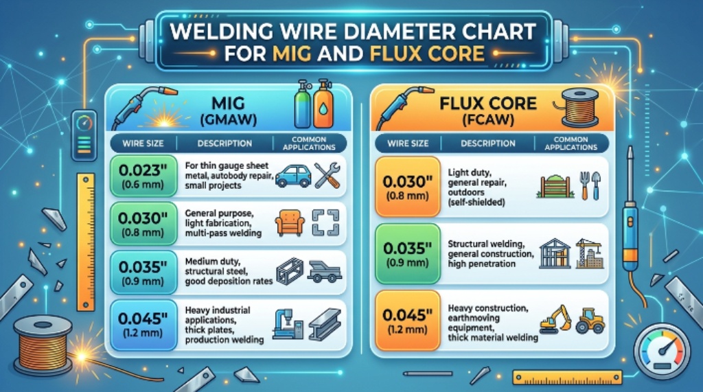
Flux Core Wire Size Chart
| Flux-core diameter | Common application | General guidance |
| .030 in | Thin to light steel | Better control for lighter work |
| .035 in | General repair and fabrication | Common all-around FCAW size |
| .045 in | Medium/heavy steel | Requires a stronger machine |
| .052 in | Heavy fabrication | Specialized/high-output applications |
The actual recommendation depends heavily on the specific flux-core classification.
For example, gas-shielded and self-shielded flux-core wires can behave very differently. Always read the manufacturer’s data sheet for:
- Polarity
- Shielding gas
- Voltage
- Amperage
- Wire-feed speed
- Welding position
- Preheat/interpass requirements
- Maximum/minimum material thickness
What Size Wire Should You Use for Aluminum?
Aluminum changes the equation.
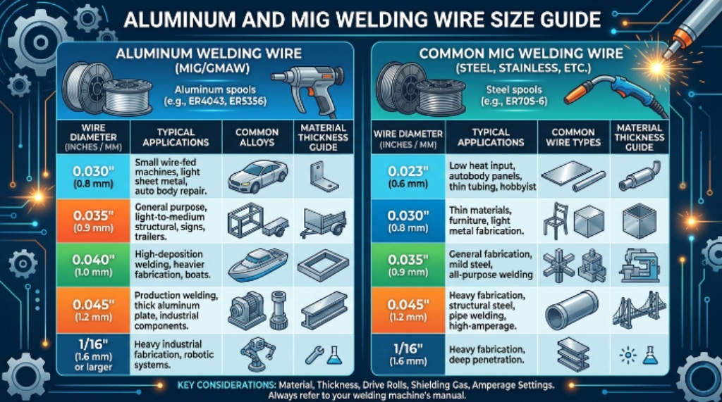
Aluminum welding wire is considerably softer than steel wire, which makes wire feeding more demanding. This is one reason spool guns and push-pull systems are common when MIG welding aluminum.
A 3/64-inch aluminum wire is a common option for many spool-gun applications.
However, don’t choose aluminum wire diameter based solely on thickness. You also need to consider:
- Aluminum alloy
- Filler classification
- Base-metal thickness
- Machine output
- Spool gun or push-pull feeder
- Shielding gas
- Contact-tip setup
- Drive-roll configuration
Miller’s aluminum welding guide provides manufacturer-specific starting parameters showing that aluminum wire diameter, alloy family, material thickness, amperage, voltage and wire-feed speed all interact. The guide explicitly describes its parameters as starting points rather than universal production procedures.
For aluminum, 100% argon is commonly used for MIG welding, but follow the filler and equipment manufacturer’s recommendations for the specific application.
How Contact Tips Affect Wire Feeding
Choosing the correct wire diameter is only half of the feeding equation.
The gun must also be configured for that wire.
Start by checking the contact tip marking. A .030-inch wire normally calls for a contact tip intended for .030-inch wire, while .035-inch wire normally uses a .035-inch tip.
But don’t blindly assume that every gun uses the same tip design. The gun manufacturer’s part number and specifications matter.
Also check:
- Drive-roll groove
- Liner
- Spool tension
- Drive-roll pressure
- Gun cable condition
- Contact-tip wear
- Wire cleanliness
A mismatch can cause symptoms that look like bad voltage or wire-feed settings.
For example, inconsistent feeding can produce:
- Burnback into the tip
- Stuttering
- Bird-nesting
- Erratic arc starts
- Excessive spatter
- Wire slipping at the drive rolls
Campbell Hausfeld’s equipment documentation likewise warns that the wire diameter should match the drive-roll groove and contact tip, because mismatches can cause slipping, binding or poor weld performance.
Drive Rolls: V-Groove vs. Knurled vs. U-Groove
Drive-roll selection is often overlooked by beginners.
For solid steel MIG wire, a smooth V-groove is commonly used.
Flux-core wire is often paired with a knurled drive roll because its tubular construction benefits from additional grip.
Soft aluminum wire generally calls for a U-groove or other manufacturer-approved aluminum feeding arrangement.
The exact configuration depends on the feeder and wire.
Do not solve a feeding problem by simply cranking down the drive-roll tension. Excessive pressure can deform softer wire or damage the wire surface.
Wire Feed Speed and Voltage: Why They Matter
Changing wire diameter usually means changing more than one machine setting.
Wire-feed speed (WFS) controls how much wire enters the arc over time. In conventional MIG systems, increasing WFS generally increases welding current because more electrode is being melted.
Voltage primarily affects arc characteristics, including arc length and bead profile.
The two settings need to work together.
If wire-feed speed is too high
You may experience:
- Stubbing
- Excessive spatter
- A harsh arc
- Poor wetting
- Wire pushing into the work
If wire-feed speed is too low
You may see:
- Burnback
- Long arc
- Inconsistent starts
- Poor deposition
If voltage is poorly matched
You can get an arc that is too short or too long, excessive spatter, an irregular bead profile, or poor fusion.
The safest approach is simple:
- Install the correct wire.
- Match the contact tip and drive roll.
- Verify polarity.
- Set shielding gas if required.
- Use the machine’s recommended starting chart.
- Make a test weld on similar scrap.
- Change one variable at a time.
- Inspect the bead before moving to the actual workpiece.
Does a Larger Welding Wire Make a Stronger Weld?
No—not automatically.
A larger wire can increase deposition capability, but weld strength depends on the complete joint and welding procedure.
A strong weld requires appropriate:
- Filler metal
- Joint preparation
- Penetration
- Fusion
- Weld size
- Welding procedure
- Base-metal compatibility
- Welder technique
Using .045-inch wire instead of .030-inch wire does not automatically make a weld stronger.
For structural or code work, the appropriate qualified welding procedure should determine the filler metal, process, parameters and joint requirements—not a generic Internet chart.
How to Choose Welding Wire Size: 8-Step Method
Instead of memorizing a chart, use this process.
1. Identify the welding process
Are you using:
- GMAW/MIG?
- Self-shielded FCAW?
- Gas-shielded FCAW?
- Aluminum MIG?
- Stainless MIG?
- Metal-cored wire?
2. Identify the base metal
Steel, stainless steel and aluminum require different filler-metal considerations.
3. Measure the material
Don’t estimate thickness by appearance. Use a gauge or caliper when practical.
4. Check your welder
Find the supported wire diameters and output range in the owner’s manual.
5. Read the wire label
Look for the AWS classification, diameter, polarity, gas requirements and recommended parameters.
6. Set up the wire path
Install the appropriate contact tip, drive roll and liner.
7. Set the machine
Use the manufacturer’s starting voltage and WFS information.
8. Test before welding the project
Make a short test bead on comparable material. Adjust the machine based on the actual arc and puddle.
This is far more reliable than copying somebody else’s settings from a different machine.
Common Welding Wire Size Mistakes
Mistake 1: Choosing wire only by material thickness
Thickness matters, but it is not the only variable.
Mistake 2: Assuming .035 is always “better”
.035 is useful, but it can be unnecessarily aggressive on thin sheet and may exceed the useful range of a small welder.
Mistake 3: Copying MIG settings to flux core
Different processes and classifications can require different polarity, voltage and technique.
Mistake 4: Ignoring the machine’s duty cycle
A machine may physically accept a spool while still being unable to run the required current continuously.
Mistake 5: Using the wrong drive roll
A wire-feed problem can easily be mistaken for a voltage problem.
Mistake 6: Skipping test welds
A chart gets you close. A test bead tells you what your actual setup is doing.
Mistake 7: Treating wire diameter as a weld-strength rating
Wire size is a setup variable, not a direct measure of weld strength.
Welding Wire Safety
Wire selection doesn’t eliminate the hazards associated with welding.
Use appropriate eye, face, hand and body protection, and control fire hazards before starting hot work.
Ventilation deserves particular attention. OSHA’s welding standard requires ventilation or local exhaust measures appropriate to the hazards and conditions of the welding operation, with additional requirements for confined spaces and certain metals or coatings.
Be especially careful with:
- Galvanized or zinc-coated steel
- Lead-containing coatings
- Cadmium-containing materials
- Stainless steel
- Painted or contaminated metal
- Oily or solvent-contaminated surfaces
- Unknown containers
OSHA specifically identifies additional ventilation requirements for zinc, lead, beryllium, cadmium and other hazardous materials.
Never weld a used drum, tank or other container unless it has been properly cleaned and made safe. OSHA expressly addresses this hazard in 29 CFR 1910.252.
FAQ: Welding Wire Sizes
What is the best welding wire size for beginners?
For general mild-steel MIG, .030-inch solid wire is a practical starting point for many beginners. If you’re primarily welding thin sheet metal, .023 or .024 inch may be easier to control.
Is .030 or .035 welding wire better?
Neither is universally better. .030 inch is often a good general-purpose choice for light and medium work. .035 inch provides greater deposition capability and is common for heavier work and flux-core welding.
What size MIG wire should I use for 1/8-inch steel?
.030 or .035-inch solid wire can be appropriate depending on the machine, joint, transfer mode and required deposition. Use the welder manufacturer’s chart rather than choosing solely from thickness.
What size welding wire is best for 1/4-inch steel?
.035 or .045 inch may be appropriate on a sufficiently powerful machine, particularly for multi-pass fabrication. The actual procedure depends on joint design, machine output and required weld size.
Can I weld thin sheet metal with .035 wire?
Yes, but it may be harder to control than .023/.024 or .030-inch wire. Higher heat input increases the risk of burn-through, especially on thin edges.
Can I use .030 flux-core wire for thick steel?
You can use smaller flux-core wire for some applications, but it may not be the most efficient choice for heavy material. Follow the specific wire manufacturer’s thickness and parameter recommendations.
Does bigger welding wire mean deeper penetration?
Not necessarily. Wire diameter changes current and deposition characteristics, but penetration also depends on voltage, WFS, travel speed, polarity, transfer mode, joint design and material.
What size wire is best for aluminum MIG?
3/64-inch aluminum wire is commonly used with spool-gun and push-pull setups, but the correct diameter depends on the alloy, thickness, filler classification and machine.
What wire size should I use with a 120V MIG welder?
Many small 120V machines are well suited to .023, .024 or .030-inch wire, depending on the manufacturer’s specifications. Don’t assume a machine can run .035 or .045 simply because the spool physically fits.
Do I need different contact tips for different wire sizes?
Yes. The contact tip should be appropriate for the wire diameter and compatible with your particular gun. Always follow the gun manufacturer’s specifications.
Can I use MIG wire without gas?
Only if you are using a wire designed for a self-shielded process, such as appropriate self-shielded flux-core wire. Conventional solid MIG wire requires shielding gas.
What is the most common MIG wire for mild steel?
ER70S-6 is a widely used mild-steel solid MIG wire classification. AWS and manufacturer documentation show ER70S-6 used in GMAW applications, while current ESAB data lists it for general fabrication and several industrial applications.
Final Welding Wire Size Chart
If you only need the quick reference, use this:
| Job | Starting wire size | Process |
| Very thin sheet | .023/.024 in | Solid MIG |
| General home-shop steel | .030 in | Solid MIG |
| Medium steel | .035 in | Solid MIG |
| General flux-core repair | .030/.035 in | Self-shielded FCAW |
| Heavier flux-core work | .045 in | FCAW |
| Heavy fabrication | .045/.052 in | MIG/FCAW, machine dependent |
| Aluminum MIG | 3/64 in is common | Spool gun/push-pull MIG |
The best wire size is ultimately the one that matches the process, filler classification, base-metal thickness, machine capability, feeding system and welding procedure.
For a beginner welding ordinary mild steel at home, .030-inch solid MIG wire is a sensible place to start. Move toward .023/.024 inch when thin sheet and burn-through control are the priority, or toward .035/.045 inch when the material and machine demand greater deposition.
Most importantly, don’t let a generic chart replace your welder’s manual. Manufacturer data, the wire manufacturer’s specification, a properly prepared test piece and—where applicable—a qualified WPS are more reliable than any one-size-fits-all Internet recommendation.